Language:


According to the pressure release button of the solenoid valve of the control box, the lifting column is automatically lowered to the same level as the ground. If the cylinder does not move or slide for a certain period of time, the downward pressure can be applied artificially until the cylinder is lowered to the ground level. 。
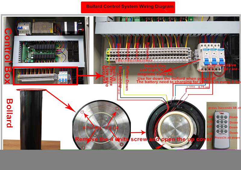
2.Wiring diagram for automatic parking bollard
3.Function set up guidance
The lift column controller must be installed in a dry environment far from strong magnetic interference, waterproof and moisture proof
remote control code description
The "learning"(学习) button on the panel is a wireless code learning button, short press-down, two led lights are always on, enter the state of the code, press a button with the remote control button at will, the led light goes out, then the code is successful, and the three key icons of the remote control rise, drop and stop.
When in the code state, if you press one short: the following board to learn the button, exit the code state and the led light goes out
Press the learning (study)button for 3 seconds long, the two led lights up and go out, clear the remote control code memory
Input description
The factory defaults to the key input. The interfaces 11,12,13 are respectively corresponding to the rising, falling, stopping, and the interface 14 is the common terminal.
Output relay description
Interface 5, 6, 7 is the output of the rising relay, of which 5 is the common end of the relay, 6 is the constant beginning, and 7 is the constant closed end;
The interface 8,9,10 is a drop relay output,8 of which is a common end of the relay,9 is a constant start,10 is a normally closed end,
Output time adjustment
The output time of the rising relay is adjusted by the knob switch a "rising time" (the default arrow of the knob switch a factory points to 3);
The output time of the drop relay is adjusted by the knob switch b "drop time", [the knob switch b factory default arrow points to 2];
Output time adjustment corresponding knob switch number 1 ≤ 9 seconds, 0 invalid. There is no need for power outage after adjusting the time.
Test model
The panel has a 3-bit dial switch, dip1 dial to off is normal mode, dip2 and dip3 are not functional. Dip1 dial to on as test mode.
[after power on, the controller circulates to output the rising and falling signal three times and then stops, and the output time corresponds to the "rise time" and "drop time" knobs. Dip1 is valid only after power off during mode switching.
Other Interface
15、16、17 is the input interface of IN1 and IN2 ;18、19、 20 is for RS485 interface
Contact: Information Center
Phone: +8615813805304
Tel: whatSapp/Wechat
Email: infors@sintronictech.com
Add: 201,Plaza A,Qianwan 1st Rd,Nanshan,Shenzhen City,Guangdong Province,China

 Alibaba Store