A 32‑bit access controller is an entry‑level core processing hardware designed for budget‑friendly access‑control system deployments. Powered by industrial‑grade 32‑bit microprocessor, it delivers fundamental data encryption, local user‑permission storage and offline access‑verification capability. As the local decision‑making unit, it processes credential signals, outputs relay trigger commands for electric locks or pedestrian turnstile gates, and saves access‑event logs locally. Sintronic 32‑bit access controllers have been deployed for overseas access‑control projects including Nigeria and Saudi Arabia small‑enterprise reference projects.
Core Working Principle of 32‑bit Access Controller
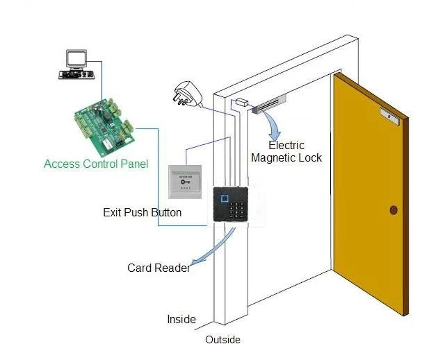
Sintronic 32‑bit access controller follows standard entry‑level access workflow: Credential Reading → 32‑bit Decryption & Verification → Permission Rule Check → Unlock / Reject Output → Event Log Recording. Full‑cycle operation steps are as follows.
1. Pre‑configuration via management software
System administrators configure parameters through Sintronic ACS‑SW access‑control software over TCP/IP LAN: import user card and biometric data, define time schedules, holiday rules, basic anti‑pass‑back and alarm settings. Permission datasets with 32‑bit‑level encryption are downloaded and saved locally to controller flash memory. The hardware supports fully‑functional offline operation if PC‑server or network connection is lost.
2. Credential reading and encrypted data transmission
Users present valid credentials: RFID IC card, fingerprint, QR‑code or facial recognition to connected readers. The reader packages credential information with 32‑bit encryption and transmits data to access controller via Wiegand or RS485 bus. This basic encryption layer defends against simple data‑sniffing risks on transmission wiring.
3. Decryption and permission validation
The access controller decrypts incoming data using built‑in 32‑bit algorithm. It matches credential ID against locally‑saved user database, and checks corresponding access authority including time zone, door permission and basic access‑control logic such as anti‑pass‑back.
4. Execution of access instruction‑ Access granted: Controller activates relay output, sends trigger signal to release electric door lock or trigger turnstile gate opening. Local LED and buzzer give access‑allowed prompt.
‑ Access denied: No unlock signal will be generated, local prompt indicates invalid credential.
5. Event log recording & optional network synchronization
Every access activity including successful entries, denied attempts and alarm triggers is saved into local memory. When LAN network is available, event logs upload synchronously to ACS‑SW software for audit reporting. If network goes offline, logs are cached locally and auto‑upload once network connection restores.
6. Alarm‑trigger processing
Door‑contact sensor monitors door physical state. In case of door‑overtime open or forced‑intrusion, the controller generates basic alarm events which can be uploaded to management PC or trigger external alarm devices.

 Indonesia
 Malaysia
 Saudi Arabia
 United States
 South Africa
 Germany
 Russia
 Italy
Italy Portugal
 Vietnam
 Zimbabwe
 South Korea
 Ruben| Project Manager | Sintronictech is good